Hmm not really. The image at the bottom of page two confirms the differences, where the capacitor goes from D- to D+, whereas my current one goes from ground to B+. But from what I've read the capacitors are apparently just to reduce radio interference.
This info should help you see if your wiring is similar:
"The main (thick) positive cable goes to the 'B+' terminal nut lug.
The main (thick) negative/earth cable goes to the 'D-' bolt which also holds the body of the capacitor.
The capacitor cable plugs onto the 'D+' spade lug.
The brush pack 'L' terminal goes out to the charge light on the dash (small white cable with red stripe on a Datsun1600).
The brush pack 'S' terminal goes directly to the battery +'ve (but I just connected it to the B+ terminal as my battery is in the boot)."
Also, does your alternator have an exciter circuit? Bosch alternators generally require a 3-4 watt globe to excite the unit. This may help your previous charge problem?
I have two ewp's and the thermos in my car, your alternator should run the thermo and ewp no worries.
I have no idea about the exciter circuit, how would I check for that? Yeah I've heard the EWPs take stuff-all power to run, so somethings up.
This exciter cct is the charge light on the dash thats connected to the L terminal.
I found a great explanantion of it:
"The Bosch alternator is incapable of self-excitation, or "boot-strapping" itself to an operating condition. Older DC generators and some U.S. alternators have residual magnetism retained in the core, or some other scheme to get enough field current to get themselves up and running. The Bosch alternator uses a different scheme. The charge warning lamp is connected between the ignition switch and the D+ terminal. When the car is first started, there is no output from the alternator at either the B+ or D+ terminals. The voltage regulator, sensing no output, is attempting to command maximum field current... it effectively shorts the D+ and DF terminals together. This places the D+ terminal close to ground potential, because the resistance of the field winding is not large. This means that there is +12 volts on one side of the charge warning lamp, and the other side of the lamp is grounded through the alternator field winding. Current thus flows through the lamp, lighting it. This same current, however, also flows through the alternator field winding, producing a magnetic field. This magnetic field is what the alternator needs to start up, and if everything is working correctly, that's exactly what happens. The alternator now begins to develop identical voltages at the D+ and B+ terminals. The D+ terminal is connected to one end of the charge warning lamp, while the other end of the lamp is connected to the battery via the ignition switch. Since the B+ terminal is hard-wired to the battery, and since both the D+ and B+ diodes are fed from the same set of windings in the alternator, no voltage difference can exist between these two points. The warning lamp goes out.
The voltage regulator "watches" the voltage at the D+ point, which should be the same as that applied to the battery. It now changes the short between the D+ and DF terminals into a variable resistance. This effectively controls the field current (whose source is now the output from the D+ terminal, and not the charge warning lamp) and thus regulates the output voltage of the alternator."


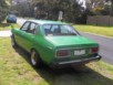
![[ img ]](http://s232.photobucket.com/user/green200b/media/SDC11965_zpse5f8695b.jpg.html)