|
Thanks for your response, but right from the very start my post included details of parts, including various part numbers / where to source them, fabrication instructions and detailed measurements. I subsequently chose not to disclose further details, and remove what I had posted in direct response to those who first laid sh*t on me for posting a disclaimer to the effect that I could not be responsible for anybody else's actions. When it comes to steering, safety is critically dependent on good engineering: unless I actually both design and build it, I cannot be responsible.
The critics then insisted that I immediately post what they wanted to see. It's quite bizarre that some hold the misguided belief that a poster is obliged to make information available on demand. Let me make it absolutely clear that as much as anybody might hold that view, there is no obligation on any poster to acquiesce to it. When it has taken considerable intellectual effort to develop a design and accumulate the associated knowledge / information, absolutely nobody has the right to demand it.
I had tried to upload a series drawings, photos and explanatory notes. Some were in .pdf and others .jpg format. The Ozdat website bounced them, indicating that they were either too large or not in a recognisable format. I've since discovered how to successfully upload such artefacts.
It is only out of respect for those genuinely interested who contacted me separately that I have agreed to post this information including lessons from over a hundred hours of engineering development effort, and some fairly tricky fabrication, needed to build a good rack and pinion conversion.
Baz’s comment on this thread acknowledges how much effort would be involved in developing a commercial bolt-up kit, which fits all requirements, engine types and etc. I would strongly agree.
This thread indicates that there is demand for a well-engineered bolt-up Rack-and-Pinion conversion. I think that many parts will have to be fabricated which would make it expensive.
My solution is achievable for less than $500 in parts, but lots and lots of time and effort in fabrication and fitting. Though this is unlikely to suit most, it should reveal some of the challenges: things to consider and some to avoid.
Though I have not tried, this conversion could well work for SR20 and FJ20 and maybe others. However, clearances are tight and both rack and engine position are critical.
It is most unlikely to suit an engine installation where the exhaust is on the right hand side (like Honda S2000): for that, the rack will have to go in front of the cross-member - a different set of issues.
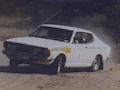
With respect to the original steering mechanism and engine cross-member configuration, see the first photo which shows one of the measurement jigs used to determine where the rack might be positioned in an attempt to replicate the original Ackermann steering. Unlike a rack which must not move, the original drag link swings under control of the Pitman and idler arms, moving side to side and front to back WRT to the body of the car as the steering is turned: it is NOT possible to use a rack to exactly replicate the OEM steering geometry. Also note that a subsequent decision was taken to have the sump at the front which required the crossmember to be reversed: this allowed a 910 sump designed to be compatible with a rack to be used, thereby allowing extra clearance between rack and engine.
I guess that a kit would have to contain something like crossmember with rack, rack rod ends, tie rod ends to suit OEM steering arms(?), ready to bolt up. Note that the chassis rails need to be reinforced, doubler plates welded to the crossmember (the flat bits at the ends of the crossmember) where it bolts up to the chassis rails, crush tubes and extra bolts installed. Steering column installation is less of a challenge, but there are constraints imposed if the original pedal box and pedals are retained. The steering column must be installed so that universal joints do not operate through excessive angles, which demands that the point at which the steering column passes through the fire wall be lower and inboard compared to the original layout. This requires enlarging the hole where the original column goes through the fire wall and welding in a plate which incorporates the mounting for the lower end of the column. The aim here is to have a line between steering wheel and pinion that is is straight as possible. A kit of parts that bolts up (no welding fabrication) would need a short steering column with two intermediate shafts between the column and pinion shaft. This might seem complicated, but offers an opportunity to achieve the most precise steering because it would have the best relationship between input at the steering wheel and rack position.
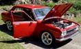
The alternative to a shortened rack like the manual TRW one from a 910 Bluebird is to go for something like a Mk1 Escort which has 1270mm track just like the 510, or go for a 240Z cross-member and rack. Both mount the rack in front of the crossmember, which is likely to be problematic if your chosen engine has the main part of its sump forward of the crossmember. The 240z track is going to be wide and parts are becoming hard to find. Another issue is that if the rack is in front of the crossmember you will almost certainly need to have compression rods to locate the lower control arms (radius rods that attach to the chassis at the rear rather than at the front), instead of tension rods (otherwise the rack rod ends, radius rods and sway bar will be competing for the same real estate). Having the rack in front of the crossmember can be done, but this involves moving the attachment points for radius rods to the back, figuring out how to avoid conflict between rack rod ends and the sway bar, and having steering arms in front of the strut: See Escort Rack photo. If considering something like an Escort rack, you need to be aware that rack rod ends use UNF(?) threads and there are two different (Imperial size) tapers used on steering arms for Mk1 / Mk2 / RS2000. These are not compatible with the metric taper (taper angle, nominal diameter and length) used in Nissan/Datsun steering arms.
I believe that the better way to go is to have the rack behind the crossmember, if a way can be found to ensure clearance between the lower intermediate shaft and the engine. With the L-series engine this works fine, and may work for others like SR20 or FJ20, but not sure. Again, it helps to have the point at which the column passes through the firewall quite low and inboard compared to the original steering column.
Also there are lots of modern front wheel drive cars that have a track width roughly the same as the P510 and mount the rack behind the engine crossmember. So there is probably a suitable rack out there (with power assist, if you prefer) - BUT lots of things must work together: splines on rack pinion must be compatible with intermediate shaft, threads at each end of rack must have suitable size and pitch, rack rod end length and threads (at both ends), tie rod end thread, tie rod end / steering arm taper, ball joints must be able to cope with angular displacement that can occur during operation, and etc., Extreme Caution is needed when it comes to angular displacement of ball joints, especially tie rod end ball joints: OEM ball joints typically tolerate 28-35 degrees total angular displacement (for racing an M14 rose joint might tolerate 28 degrees whilst a special 'high displacement' rose joint might tolerate more than 50 degrees). It is critically important to measure these angles precisely for your specific steering/suspension set-up and for the full ranges of suspension travel and steering: GET THIS WRONG AND YOUR STEERING COULD BREAK!
If you are looking for a really simple bolt-up solution: I don't think there is one.
| Attachments: |
File comment: Measuring rack position to determine if it is possible replicate OEM steering geometry.
![[ attachment ]](./download/file.php?id=31625&t=1&sid=e3defd6e4cf9ab06e22a56b80baa55c0)
3Rack-cf-OEMSteering.jpg [ 1.48 MiB | Viewed 7103 times ]
|
File comment: Configuration of Escort Rack (viewed from the front of the car). Here rack is in front of engine cross-member. For rotary or S2000 Honda installations, having the rack in front of the cross-member may be the only way.
![[ attachment ]](./download/file.php?id=31516&t=1&sid=e3defd6e4cf9ab06e22a56b80baa55c0)
Escort MK1 RS1600 Rack.jpg [ 207.89 KiB | Viewed 7172 times ]
|
File comment: Rack installed behind 510 crossmember that has been reversed and LCA pivots moved slightly outboard. Alloy plate, solidly bolted to the cross-member, firmly bolts up to the chassis via brackets (not shown) at the OEM steering box and idler arm mounting points. This is for strength and rigidity under conditions of high lateral loading, hence extra safety: it is not designed as a bash plate!
![[ attachment ]](./download/file.php?id=31486&t=1&sid=e3defd6e4cf9ab06e22a56b80baa55c0)
RackXmem.png [ 1.16 MiB | Viewed 7249 times ]
|
_________________
Things work best when it matters the least, and ...
Last edited by AlanDatsomefun on Fri May 15, 2015 10:52 am, edited 57 times in total.
|